Electrical Circuits and Safety
Circuit components
Know each component’s circuit symbol and function:
| Component | Function or behaviour | Symbol |
|---|---|---|
| Cell, battery, d.c./a.c. supply | Provide electrical energy; cells in series combine e.m.f. | 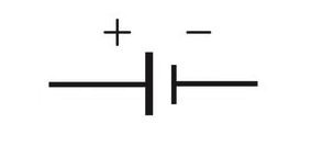 |
| Generator | Converts mechanical energy to electrical energy. | 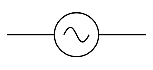 |
| Switch | Opens or closes a circuit. |  |
| Fixed/variable resistor | Opposes current; variable resistance controls current. | 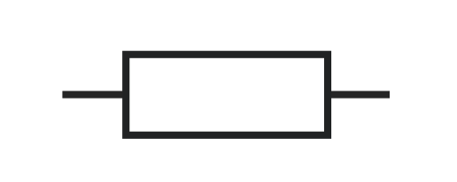 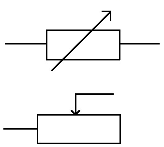 |
| Heater, lamp, motor, bell | Transfer electrical energy to thermal, light, mechanical, or sound energy. | 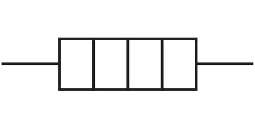 |
| NTC thermistor | Resistance decreases as temperature increases. | 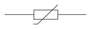 |
| LDR | Resistance decreases as light intensity increases. | 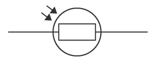 |
| Ammeter/voltmeter | Measure current in series. |  |
| Voltmeter | Measure p.d. in parallel |  |
| Diode/LED | Allows current mainly one way; LED emits light when forward biased. | 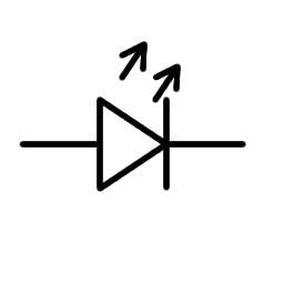 |
| Magnetising coil/relay | Produces a magnetic field; relay uses it to switch another circuit. | 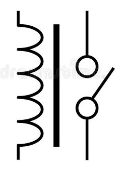 |
| Transformer | Changes a.c. voltage using electromagnetic induction. |  |
| Fuse | Melts and opens the circuit if current is too high. | 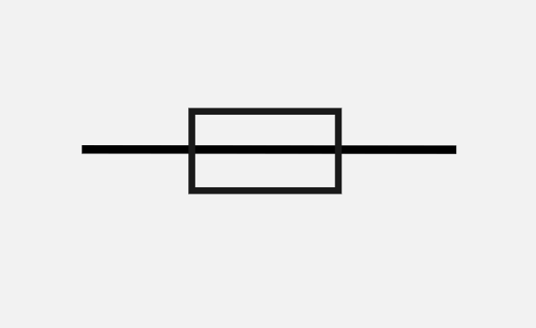 |
A circuit diagram uses standard symbols and clear connecting wires. A potential divider is a series arrangement of resistors or a resistor and sensor.
Series and parallel circuits
Series Circuits
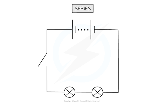
In a series circuit, current is the same everywhere:
$$ I=I_1=I_2 $$
Cells connected in series in the same direction have combined e.m.f. equal to the sum of their e.m.f.s. Two 1.5 V cells in series provide 3.0 V. Resistors in series have:
$$ R_T=R_1+R_2+\cdots $$
The Supplement rules are that the supply p.d. equals the sum of component p.d.s:
$$ V_T=V_1+V_2+\cdots $$
Parallel Circuits
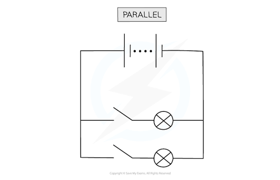
In parallel, current divides at a junction and source current is greater than any one branch current:
$$ I_T=I_1+I_2+\cdots $$
The p.d. is the same across every branch.
$$ V = V_1 = V_2 = … $$
For two or more resistors:
$$ \frac1{R_T}=\frac1{R_1}+\frac1{R_2}+\cdots $$
Therefore parallel resistance is less than the resistance of any single branch. For 3 Ω and 6 Ω in parallel, $R_T=3\times6/(3+6)=2\ \Omega$.
Domestic lighting circuits are parallel: each lamp receives the supply p.d., can be controlled independently, and keeps working if another lamp fails.
Potential dividers and sensors

A potential divider is a series circuit that shares a supply p.d. between two resistors. The current is the same through both resistors. At constant current, a larger resistance has a larger p.d. because $V=IR$. The output can be measured across either resistor; changing the output connection changes how the voltage responds.
For output $V_1$ across $R_1$:
$$ V_1=V\frac{R_1}{R_1+R_2} $$
If $R_1$ increases while $R_2$ stays fixed, the p.d. across $R_1$ increases and the p.d. across $R_2$ decreases. The two output p.d.s always add to the supply p.d.
Worked example: With $V=6.0\text{ V}$, $R_1=2.0\text{ k}\Omega$, and $R_2=4.0\text{ k}\Omega$, the output across $R_1$ is $V_1=6.0\times2/(2+4)=2.0\text{ V}$.
The p.d. across $R_2$ is therefore $6.0-2.0=4.0\text{ V}$.
A variable potential divider, or potentiometer, has a sliding contact. Moving the contact changes the resistance ratio and varies the output smoothly from near $0\text{ V}$ to nearly the full supply p.d. It is used in controls such as volume or brightness adjustment.
Sensor dividers
A sensor replaces one resistor so that environmental changes alter the output p.d. The output direction depends on which component is connected to the voltmeter.
- An LDR has high resistance in darkness and low resistance in bright light. If the output is across an LDR connected as $R_1$, the output is high in darkness and low in bright light.
- An NTC thermistor has high resistance when cold and low resistance when hot. If the output is across the thermistor, the output is high when cold and low when hot.
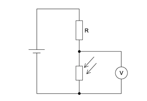
Worked example: A 12 V divider has a fixed $4.0\text{ k}\Omega$ resistor and an LDR as $R_1$.
In darkness: $R_{LDR}=8.0\text{ k}\Omega$, so $V_{out}=12\times8/(8+4)=8.0\text{ V}$.
In bright light: $R_{LDR}=2.0\text{ k}\Omega$, so $V_{out}=12\times2/(2+4)=4.0\text{ V}$.
An electronic switch or relay can respond when the output crosses a chosen threshold, for example switching a street lamp on when it becomes dark.
Electrical safety
Hazards include:
- Damaged insulation: exposed live wire can cause electric shock or contact another conductor, causing a short circuit and fire.
- Overheating: excessive current or a tightly coiled cable heats the wire; insulation may melt and nearby material may catch fire.
- Damp conditions: water lowers the resistance of a person’s skin, increasing shock current.
- Overloading: too many appliances draw excessive current, overheating the cable and creating a fire risk.
A mains cable has:
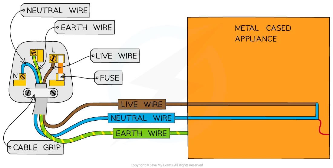
- live: high alternating p.d.; the dangerous supply wire;
- neutral: returns current and is near zero p.d.;
- earth: safety wire connected to a metal case and normally carrying no current.
A switch and fuse are connected in the live wire. The live wire brings the high p.d. to the appliance, so opening a switch in this wire separates the appliance from the dangerous supply. If the switch were placed only in the neutral wire, current would stop, but parts inside the appliance could still be connected to the live p.d.
A fuse contains a thin piece of wire. During normal operation, its current is below its rating and the wire stays intact. If a fault or overload causes excessive current, the wire heats up and melts, opening the circuit. This stops current before the cable becomes dangerously hot. Choose a fuse rating just above normal operating current but below the safe current for the cable; for a normal current of $2\text{ A}$, a $3\text{ A}$ fuse is suitable. A trip switch performs a similar protective job by opening the circuit automatically when current becomes excessive; unlike a fuse, it can be reset after the fault is cleared.
A metal-cased appliance is earthed. The earth wire connects the metal case to a low-resistance safety path. If a loose live wire touches the case, a large current flows through the earth wire instead of through a person touching the case. The fuse melts or the trip switch opens, disconnecting the supply and making the case safe. The earth wire normally carries no current; it carries fault current only.
An appliance with a non-conducting plastic case may use double insulation instead of an earth wire. Its outer case and internal insulation provide two layers of protection, so a person cannot touch a live conductor even if an internal wire becomes loose. Such an appliance uses a two-core cable containing live and neutral only. Its fuse is still needed to protect the cable from excessive current.
Atributions: Ampere icons created by mattbadal