Simple magnetism
Poles and materials
Like magnetic poles repel. Unlike poles attract. Magnetic materials can be attracted to a magnet and can become magnetised; non-magnetic materials are not attracted.

- Soft iron is easy to magnetise and demagnetise. It is used for temporary magnets and electromagnets.
- Steel is harder to magnetise but keeps its magnetism. It is used for permanent magnets.
- Induced magnetism occurs when a magnetic material becomes magnetised in an external field. The end nearest a magnet becomes the opposite pole, so the material is attracted.
Magnetic fields
A magnetic field is a region where a magnetic pole experiences a force. Field direction is the direction of force on a north pole. Around a bar magnet, field lines go from north to south outside the magnet. They never cross. Lines closer together show a stronger field.
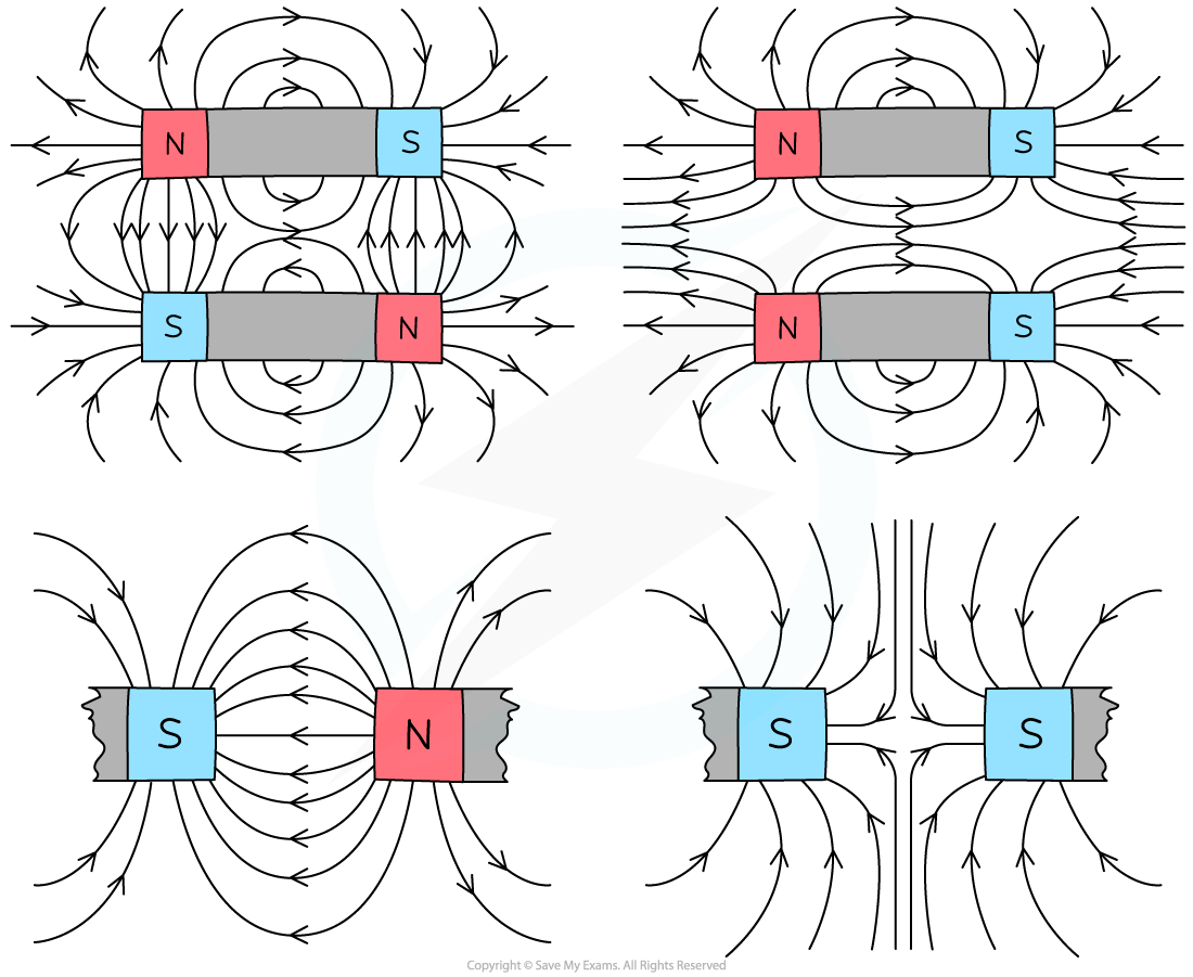
A compass shows the direction of a field. Iron filings show its pattern. Magnetic fields interact, producing forces between magnets and magnetic materials. Permanent magnets are used in compasses and some speakers. Electromagnets are useful where a field must be switched, varied, or reversed, such as in cranes, relays, motors, and loudspeakers.
Electromagnetic induction
What happens
An e.m.f. is induced when a conductor cuts magnetic field lines or when the magnetic field through a coil changes. If the circuit is complete, the induced e.m.f. produces a current.
Demonstration: Connect a coil to a galvanometer and move a bar magnet into the coil. The galvanometer deflects while the magnet moves. Hold the magnet still and the pointer returns to zero: a stationary field does not produce a sustained e.m.f. Move the magnet out again and the deflection reverses.
Increasing the induced e.m.f.
The induced e.m.f. is larger when:
- the magnet or conductor moves faster;
- the magnetic field is stronger;
- the coil has more turns.
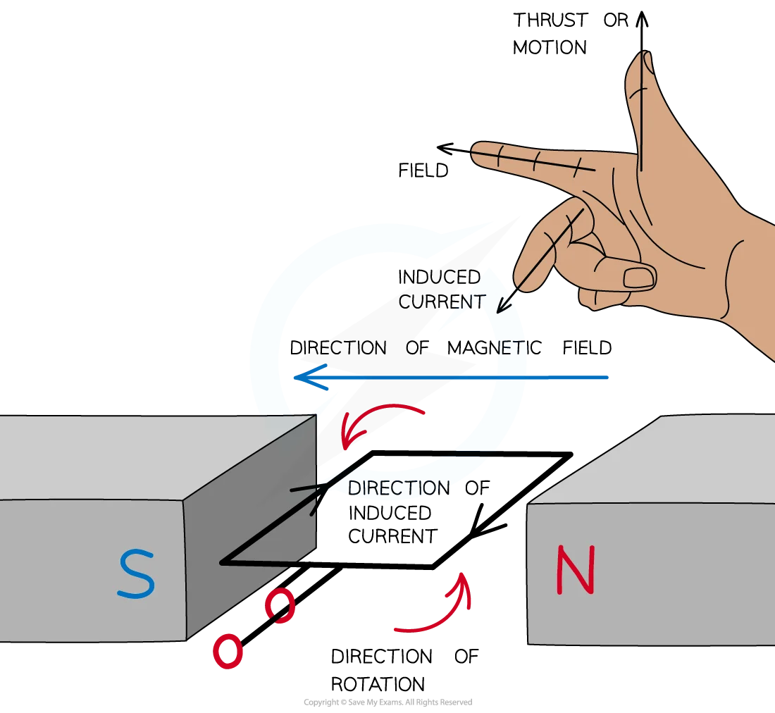
The induced e.m.f. and current oppose the change causing them. Fleming’s right-hand rule gives relative directions: thumb is conductor motion, first finger is magnetic field, and second finger is conventional current. Reversing the motion or field reverses the induced current.
A.C. generator
An a.c. generator changes mechanical energy into electrical energy by electromagnetic induction. (Fleming’s right-hand rule in diagram)
Construction
A simple generator contains:
- a rectangular coil that can rotate between the poles of a magnet;
- an axle or handle to provide mechanical rotation;
- two slip rings attached to the two ends of the coil;
- two stationary carbon brushes pressing on the slip rings;
- an external circuit connected to the brushes.
Each slip ring stays connected to one end of the rotating coil. The brushes do not rotate; they maintain electrical contact with the spinning rings and carry the output to the external circuit. Slip rings allow the connections to the coil ends to remain continuous, so the output can reverse direction.
How the event produces a.c.
- Turning the axle rotates the coil in the magnetic field.
- The two long sides of the coil cut field lines, so an e.m.f. is induced.
- The e.m.f. passes through the slip rings and brushes to the external circuit.
- After half a turn, each side of the coil moves in the opposite direction through the field.
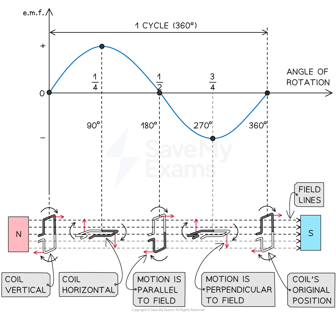
- The induced e.m.f. and current therefore reverse direction every half-turn. This is alternating current.
The e.m.f. is zero when the coil sides move parallel to the field and cut no field lines. It is maximum when the sides cut the field fastest. The output graph alternates above and below zero. Faster rotation, a stronger field, or more turns increases the peak e.m.f.
A generator uses slip rings. A d.c. motor uses a split-ring commutator, which is designed to reverse current in the coil so the turning effect stays in one direction.
Magnetic effect of a current
Straight wire and solenoid
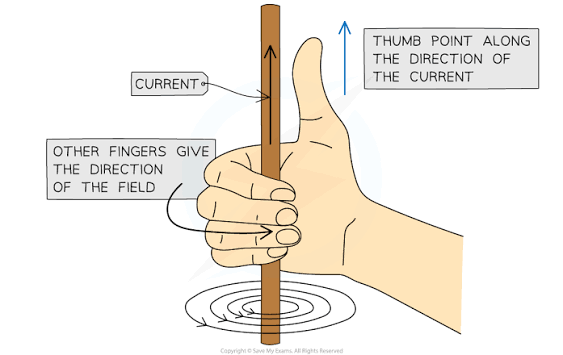
A current in a straight wire produces concentric circular magnetic field lines. Reversing the current reverses the field direction; increasing current strengthens the field.
A solenoid is a coil of wire. Its field is like the field of a bar magnet, with a north and south pole. Its field becomes stronger when current increases, when there are more turns per unit length, or when a soft-iron core is inserted.
Relay
A relay uses a small control current to switch a separate circuit:
- The control current flows through a coil.
- The coil becomes an electromagnet.
- The electromagnet attracts an iron armature.
- The armature moves contacts and opens or closes the second circuit.
This lets a low-current circuit control a higher-current circuit safely.
Loudspeaker
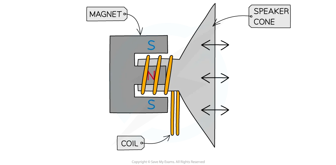
A loudspeaker has a coil placed in the field of a permanent magnet. A changing audio current changes the magnetic force on the coil. The coil moves backwards and forwards, moving the cone. The vibrating cone produces sound.
Force on conductors and charged particles
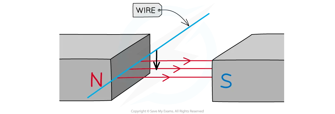
A current-carrying conductor in a magnetic field experiences a force. To demonstrate it, place a current-carrying wire between magnet poles and observe its movement. Reverse the current or the magnetic field and the force reverses. Increasing current or field strength increases the force.
Fleming’s left-hand rule gives the relative directions:
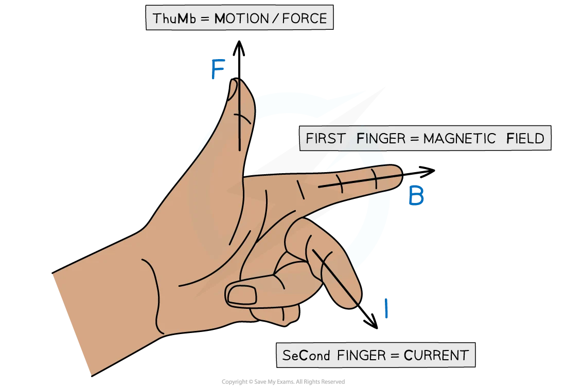
- first finger: magnetic field;
- second finger: conventional current;
- thumb: force or motion.
A beam of charged particles also experiences a force in a magnetic field. Reversing the direction of charge movement or the field reverses the force, so the beam can follow a curved path.
D.C. motor
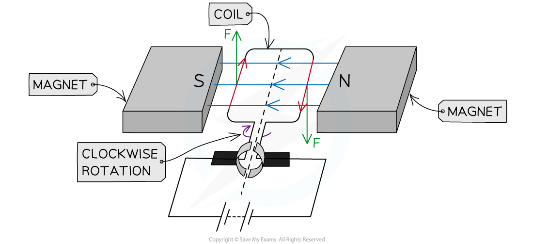
A d.c. motor changes electrical energy into mechanical energy.
- Current enters a coil between the poles of a magnet.
- The two sides of the coil carry current in opposite directions.
- The magnetic field exerts opposite forces on the two sides.
- These forces create a turning effect and rotate the coil.
- After half a turn, the split-ring commutator reverses the current in the coil.
- The forces continue turning the coil in the same direction.
Carbon brushes press against the commutator and maintain contact with the rotating coil. More turns, greater current, or a stronger magnetic field increases the turning effect.
Transformer
A transformer changes the size of an alternating voltage without moving parts.
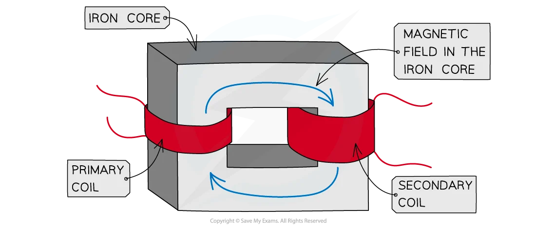
How it works
- An alternating current enters the primary coil.
- The primary coil produces a continuously changing magnetic field.
- A soft-iron core guides this changing field through the secondary coil.
- The changing field induces an alternating e.m.f. in the secondary coil.
A transformer requires a.c. A steady d.c. produces a constant field after the initial switch-on change, so it does not produce a continuous secondary e.m.f.
For an ideal transformer:
$$ \frac{V_p}{N_p}=\frac{V_s}{N_s},\qquad I_pV_p=I_sV_s $$
- Step-up transformer: $N_s>N_p$, so output voltage increases.
- Step-down transformer: $N_s<N_p$, so output voltage decreases.
Worked examples:
A transformer has $V_p=12\text{ V}$, $N_p=600$, and $N_s=3000$.
Therefore $V_s=12(3000/600)=60\text{ V}$.
If the primary current is 5.0 A, an ideal transformer has $I_s=I_pV_p/V_s=5.0\times12/60=1.0\text{ A}$.
High-Voltage Power Transmission & Efficiency
Electricity is transmitted at high voltage and low current. For cable resistance $R$, power loss is:
$$ P_{loss}=I^2R $$
A transmission cable carrying 10 A with resistance 0.50 $\Omega$ loses $P_{loss}=10^2\times0.50=50\text{ W}$. Stepping up voltage reduces current for the same power, so transmission heating losses are reduced. A step-down transformer then supplies a lower voltage for users.
System Flow:
Power Station $\rightarrow$ Step-Up Transformer (High Voltage / Low Current for transmission) $\rightarrow$ National Grid $\rightarrow$ Step-Down Transformer (Low Voltage / Safe Current) $\rightarrow$ Homes.